1.21.2011

yellow sealer tape

To make good headway on completing the galley booth, I had to break out the 8 x 12 ft vac bag table and perform another marathon session.  This time, I decided to maximize the entire surface area by nesting the panels together so that they pretty much consumed the entire surface area of my table. For this mega vacuum bag, I used vac bag membrane on top and bottom because I was not sure that my table was completely air tight.  This took two rolls of yellow sealer tape.......say that ten times:   "Yellow sealer tape" "Yellow sealer tape""Yellow sealer tape""Yellow sealer tape""Yellow sealer tape""Yellow sealer tape"..........too much time in the shop makes Jack a dull boy.

booth panels

Again......another impromptu post cure oven


1.19.2011

no place to sit...

After careful attention to human factors and proportion, what took about two days to put together came apart in about 5 minutes. Reason being is that the interior booth seating shapes have to be sheathed with bi axial glass and epoxy to give them strength.  Once the entire seating area is finished it will only weigh about 25 lbs.  If it were built in conventional plywood, I imagine it would weigh in at over 75 lbs. ...simplify and add lightness is still the mantra. The booth is constructed of structural foam sheathed with epoxy and glass and will be upholstered in a doe leather marine-tex.

An experiment in the reduction of production time

Faced with the prospect of having to laminate over 25 separate panels for the interior bridge deck galley area, I decided to run an experiment in vacuum bagging multiple layers and panels all under one vacuum bag. Did it work? I think it did but given the marathon layup session and a bit of a hassle peeling all the layers of peel ply perf and breather off,  I'm not sure if I'll be so bold in the future.

Here's the result:

That's a total of 11 separate panels laminated front and back and stacked all under one vacuum bag.

It went like this: 

lower part of the bag ( vinyl flooring on a temp floor panel)
plastic membrane to keep the lot from sticking to the vinyl flooring
peel ply
glass
foam
glass
peel ply
perf
peel ply
glass
foam
glass
peel ply
perf
peel ply
glass
foam
glass
peel ply
perf
breather
top vac bag.
beer

I think it was worth it because it would have taken me at least a week to use the peel ply bondo spreader method to bond both sides of the 11 panels that I made in one night. 

Here's a few tricks that I learned.
pull the individual groups of panels up and lean them against something
I used a few wooden wedges to separate the groups of panels
( this wasn't that difficult)
score the individual panel edges with an angle grinder on both sides along the panel seams then pop them apart like sheet rock.
After pulling off all the peel ply, I did have a few flaws where excess resin gathered but nothing a little sanding won't fix.

would I try this again?  Maybe not.  I may just turn on some good music and lay some panels up one at a time for a while.  If I were in a race to produce the most panels in a day I may give it another go but I can think of a few more enjoyable ways to spend an evening.


1.18.2011

More icebox excitement

True.....how exciting can an Icebox be?
For effect, imagine you were a hundred years back in time and you told someone that you could make ice from sunshine and wind. ( solar panels and wind generators).....now that would be more exciting.

Here's the box with the last round of glassing which makes her 100 percent part of the integrity of the boat. The location of the unit actually provides structure to the cabin bulkhead itself and if I ever get blue water smashing against the outer cabin bulkhead, I'm confident that this unit will act as a dresser drawer against a door knob.

All the box components are now bonded together and peel ply was used to minimize the sanding required to prep the sides for a caramelized bamboo veneer that I have chosen as a final finish.  The top work surface will be covered with "Wilson Art" bottle glass Formica and once the insides are glossed over with white epoxy, I'll load it with the works: condenser, compressor, keel cooler, and a spill-over thermostat for the refrigerator portion.  


I've chosen a 40 inch condenser plate and followed the instructions to bend 3 in. dia corners so that it can be mounted inside the ice box so that it will allow one half of the box to be a freezer and the other half the fridge.. Note the keel cooler on the left.

1.11.2011

Fridge / freezer box: a plan from top to bottom


From all manner of sources, an important aspect of any top loading fridge / freezer is a double sealed top. In my case I created the profile by using three different thicknesses of foam which I will glass and vacuum bag to create a wrap around top that I will bond to the flush top of the cabinet. The next few steps will be to build the butterfly opening top with double seals, bond a Formica laminate to the top surface of the cabinet box and top, apply a two ply bamboo veneer to the outside of the box for cosmetics then finish the box with an aluminum strip of edging to give it a nice professional look. 

From top to bottom, here's my plan:
  1. icebox top surface smoothed to accept chamfered opening ( steps 2, 3 and 4)
  2. nest layer of 3/4 in dyvinicell foam,  1 1/4 inch beveled layer of foam
  3. 1/4 inch spacer which will be covered with 6 ply cabinit grade plywood
  4. final surface laminate to top
  5. veneer exterior cabinet
  6. install edging
  7. apply internal glazing ( a simple rolled on mixture of epoxy, titanium dioxide and cabosil to prevent "running" This I have found produces a thick, rock hard glossy surface that is easy to clean and avoids all the labor of having to spray expensive automotive coatings such as deadly polyurethane imron or synthetic enamels. 
  8. Install the guts ( a modular Fridgoboat system http://frigoboat.com/)
  9. Install evaporator
  10. Components: (The guts)
  11. 200F Evaporator - 40.25"w x 10.5"h, Flat Plate
    install compressor

  12. K50-AEO with AEO control 
    (This unit has an electronic "smart" speed control that automaticly adjusts the compressor RPM to provide the precise amount of refrigeration necessary for the job at hand so that the unit runs at a lower rate for a longer time thereby creating higher efficiencies than if it were to rune wide open for shorter times.) 

  13. install keel cooled condenser to prevent cabin heat buildup in the tropics
  14. Keel Cooler thread-mounted condenser
    Install freezer thermostat
    Thermostat, Coastal Digital Fahrenheit and Celsius 12v
  15. Install spill over unit
Spillover fan/thermostat kit, mechanical


This device pulls cold air from the freezer section and dumps the right amount of chilled air into the refridgerator portion while excess air flows back into the freezer portion.  This thermostat can be set above freezing while the freezer unit can be set well below freezing as desired....
    I plan on trailing a fishing line off the transom and packing this freezer with fish for my family. Not to mention "ice for the blender that will soon render that tropical concoction that helps one hang on"

    1.10.2011

    pouring the foam

    Here's the fridge / freezer cabinet after positioning the ice box in place and pouring a 2 lb /ft ^3 expanding polyurethane foam. I measured out enough to fill the bottom and then started filling the side cavities with smaller batches until the foam expanded up beyond the top. I then ran a hand saw around the top to level the foam. This fridge / freezer will have a butterfly top that will allow individual access to each compartment.  

    1.08.2011

    Roughing in the Fridge / Freezer

    I chose to place the fridge right next to the cabin door so that cold drinks can be readily available to the skipper.

    The interior panels have been sheathed one side with a 12 oz. biaxial glass and epoxy.  To prevent infra red  heat absorption, the inner side of the outer cabinet will be lined with a thin aluminum foil. The surrounding void between the ice box shell and the cabinet will then be filled with a two part expanding polyurethane foam.  

    1.06.2011

    mocking up the cabin booth seating

    Here I am making a layout of the seat profile that I will build inside the cabin. I spent countless hours studying human factor design books in order to insure that when I want to kick back and have some cookies and milk, I'll be nice and comfortable.

    12.31.2010

    Modern art Hatch Openings

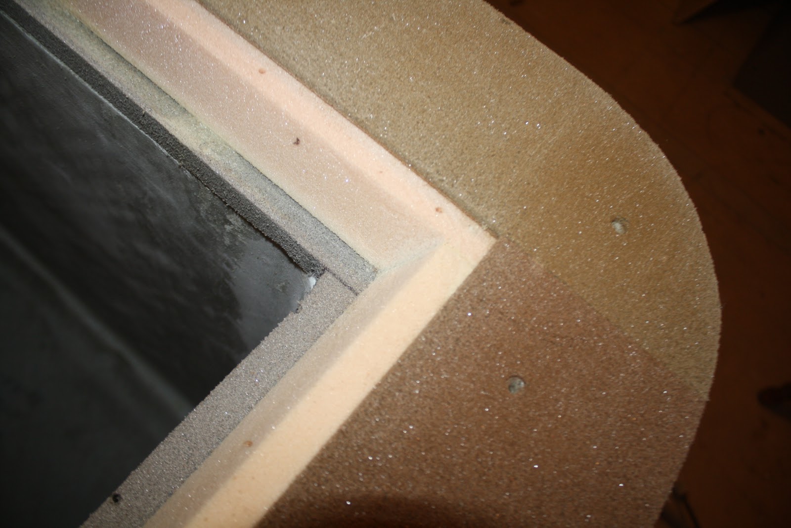
     I strengthened the edges of all of the hatch openings by routing out an inch and a half of deck foam then re-filling the void with a thixotropic mixture of aerosil, glass micro spheres and epoxy.


    I then used strips of tough synthetic roof material as a mold to create nice smooth edges that will require little finish work.  I used flexible wood strips, springing them together to hold the edges in place.

     this method works really well.  The sharpy marks will be the drill holes and location of the hatch frames.


    12.29.2010

    Shame on Lewmar

    flimsy hinge clutch attachment on new Lewmar escape hatches:

    I can only hope that this failure was due to a worker using the wrong size rivet, otherwise, Lewmar should know better than to use such a failed design in the attachment method of the hinge clutch to the frame.


    It is easy to see that the flimsy aluminum rivets were not long enough to even go through the flange on the hatch frame. 


    This two part "spring/clutch" is attached between the two hinges and is supposed to keep the hatch from swinging wildly when opened. In my case, the second time I opened the hatch, the attachment broke off.  

    This is very poor design. At close to a thousand dollars a piece, it is not unreasonable to believe that details like this would be so under designed. 

    Yet another opportunity to improve upon the work of a manufacturer.......Tomorrow I will bring the escape hatch to the local farm and ranch hardware store and buy two beefy stainless steel fasteners to replace these two flimsy rivets......only down side will be galvanic corrosion due to dissimilar metals but I may not have a choice. 

    12.21.2010

    Got to have a place for the Frozen fish and some cold beer.


    I took a little time to create a CAD drawing of the type of fridge / freezer that I want to have on board and I'm planning on building it in the next week.  I'm hoping that it will come out looking something like this.  I'll be chopping foam, slinging tape measures around like swords and knocking this thing out free style.


    I've been doing a fair amount of studying about marine fridge freezer systems and I've decided to build my own.  A helpful book that I just read was "Refrigeration for Pleasure Boats" by Nigel Calder.  It is a pretty basic book but gives some nice illustrations of simple boxes.  I chose a full "Frigoboat" component system because I like the idea of the pre charged lines, electronic speed control option that reduces the compressor RPM to meet the demand and I liked the modular aspect.  Also, since I'm headed south, I'm using a keel cooler condenser to dump the heat into the water rather than heating up the cabin.  

    12.20.2010

    Coooooold


    Here's my excuse for my delayed progress on the Cat.....It's fricking cold and I am a misplaced Southerner born and breed.
    Here are a few projects that haunt me:
    1. Boxing in the swing up rudders
    2. building the top loading fridge freeze boxes with Frigoboat mechanicals w/ keel cooler
    3. glassing strips supports for hull floor boards
    4. finishing out all four state rooms
    5. coordinating the build of the mast, boom and standing rigging ( Ballenger Spars)
    6. Overseeing sail construction ( Doyle Sails)
    7. detailing engines:  exhausts, filters. through hulls, etc.
    8. installing R.O. watermaker
    9. Building out interior bridge-deck living space
    10. Electrical system ( planning on keeping it simple )
    ...........but who's counting?

    12.11.2010

    floor board strips

    This is a shot taken about knee level from the inside of the starboard hull looking into the forward  cabin.  A cross wise lower hull stiffener will also be glassed in place mid ways between the forward bulkhead and the mast bulkhead.  Once this stiffener is in place, I will glass over the floor board strips that I have glued in place and which will support the floor boards. 

    12.09.2010

    Dancing super models


    Since it's winter time in the Pacific NW, the main cabin has become my new shop.  I covered the floor with 6 mil plastic sheet to keep from getting drips of epoxy everwhere.

    There are a total of 12 floor boards in this boat and each one will be glassed and vacuum bagged to save weight and just in case, to withstand the compressive forces of 20 dancing super models wearing high heels.....that's 40 high heels. Given the average weight of a super model of say 65 lbs, and the area of the average high heel being  1/2 in x 1/2 inch this introduces the very real possibility of sustaining pressures on the order of  265 lbs per inch ^2 on the composite laminate ........or further still if the dancers perform moves that require high stepping , the pressure of a dancer standing on one high heel may soar to 536 lbs per in ^2 . ......  Perhaps a placard next to the US coast guard "no discharge notification" should read. "When dancing, all Super-models should refrain from high-stepping along both the port and starboard floor boards".

    If I do two panels at at time per day, that's only six days........"only six days he says!"  Like I always say, if it's cold and raining outside you may as well be vacuum bagging dance floor boards.....I'm always saying that......I wish I could stop saying that

    Double  Vacuum lines


    heating the interior of the boat to cure the two panels.


      260 # / in^2 potential destructive pressure.


    12.08.2010

    both of the twin diesels are in bed now

    I distributed the load of each engine by supporting a 4 x 4 in three places and used a chain hoist to allow me to wiggle the engine into place. 

    Starboard side engine resting in a gloss white engine bed.

    12.07.2010

    Putting the engines to bed

     2 x 6 cross beam with rolling trolley

     sliding the engine down into the hull

     Walking the engine down a plank to it's bed.

     Using a 4x4 positioned over the aft cabin hatch, I was able to inch the  port side Engine into its place......

    In order to allow me to quickly diagnose possible engine problems due to oil or  fluid leaks, I decided to lay  down a  gloss white epoxy coating inside the engine compartments.  To do this,  I mixed 2 quart of A side epoxy with one quart B side epoxy then mixed 1 cup of Titanium dioxide powder along with 1 cup of cabosil to create a thixotropic hard coat epoxy "paint". I then rolled it on nice and thick.   Now I should be able to wipe this surface down clean every time I check the engines.


    12.02.2010

    Escape hatches


    Each hull requires an escape hatch and rather than install them so that they extend beyond the hull exterior, it is suggested that a recessed flange be used to allow the escape hatch glazing to be flush with the hull.  These foam pieces will be glassed in place creating a rigid, flat  location to bolt the medium profile Lewmar escape hatches.


    Engine comes out of it's crate.

    Two brand new 3 cylinder, sail drive, diesel engines were removed from their crates.  Seen here is one of the Yanmar 3YM-20 engines. This particular engine is destined for the starboard side hull. For installation, I decided to just man handle the units in place through the cabin doors rather than cut and build flush hatches in the aft decks above boarding stairs.  If I ever need to re build them,  I'll just take the darn things apart and remove them bit by bit.

    11.25.2010

    Import Security Fileing...or else

    A week ago, I mistakenly mentioned that my cat's mast had left the port of Tauranga, NZ on the ANL Bindana when in fact, this was when the mast was packed into the container.  The ship is still in port:  see link-

    http://www.marinetraffic.com/ais/default.aspx?zoom=9&oldmmsi=636091168&olddate=11/24/2010%201:52:07%20AM

    The US now requires that an Import Security filling ( ISF) be filed before any item is shipped and imposes a $5000.00 fine if not done.   I hope that the documents made it into the right hands........

    11.23.2010

    Decks and cabin tops sealed w/ Awlgrip

    Deck primed and sealed w/ AwlGrip 545. One of the twin diesel engines can be seen below the bridgedeck awaiting installation. It will be nice to tuck them into their engine beds so I won't keep putting random  tools and clutter on top of the crates.


    The cabin tops and foredeck seen here in 545 sealer. The gallon paint cans are placed on deck for scale. The black window covers are actually the cut outs with flat black paint. I set them back in place to allow me to heat the interior this winter.