Tubes glassed in place showing stainless steel removable pivot pin
trial fitting of the port side rudder box
installing the shear tubes
filleting the tubes prior to glassing them in place
close up of stainless shear pin tubes. I've used a couple of pieces of synthetic roofing material, some sheet foam and a little peel ply to help mold the epoxy/micro mixture in place. When cured, I'll remove the sheet material, rip off the peel ply and give it a final shaping before glassing the tubes in place.
When complete, cedar dowels will be inserted so that if the rudders should happen to strike something, the dowels will shear, allowing the rudder boxes to kick up instead of bending or breaking the rudder shaft.
After building up the corners of the rudder boxes with a good thick mixture of micro balloons, cabosil ad epoxy, I was able to use a thick commercial roofing membrane as a mold to keep the mixture in place.
With the remainder of the same batch, I filled the edges of the upper rudder bearing access hatches.
To dig out the edges of the laminated pieces, I discovered a tool that has actually become very useful.
It's a power band file ( basically a small hand held belt sander that is highly adjustable and makes it possible to sand and remove material from very secluded areas. This tool is available from Harbor freight Tools for a guilt producing price of $29.00 seen here :
I find it very clever that a Chinese manufacturer would name the brand of a tool for a large city in the United States........It would leave you to believe that you are supporting the US economy by buying "local". It's also very amazing how small they can print the words "MADE IN CHINA" on a sticker.
prep work required to laminate 5 layers of bi-directional glass over the stainless pivot tubes
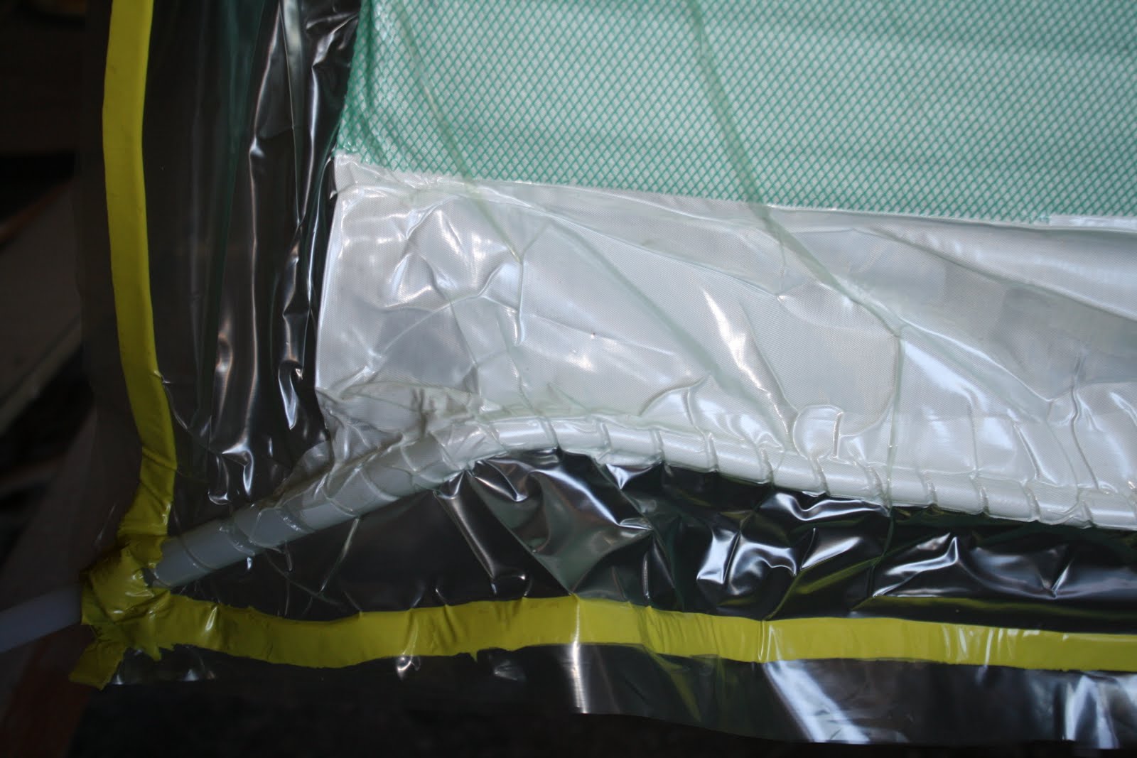
a close up of the very odd way that I had to wrap the pivot tubes. Sometimes the order in which you build things is very important. As you can see, I boxed myself into a corner and had to hog out a slot so that I can slide saturated glass in place sideways . The yellow goo is vacuum seal tape placed so that resin will not get into the pivot tube. The tube sections were bonded in place first with a rod that insured alignment.
With all due respect for the confidentiality of the design, I have included an illustration of the rudder box as shown in the plan set. I have removed all technical notes but include these illustrations so that one can get a better idea of the end result.
At long last. Here I am with the finished rudders. Next, I'll skim them over with a little fairing compound, sand them smooth and prep them for a good coat of anti fouling paint.
The lower portion of the kick up rudder boxes are just below the water line so in order to prevent the internal void from partially filling with water, I used two part foam as fill. While I was at it, I also decided to completely fill the aft void as well thinking that if the box were ever to break loose and crack, it would float and it may allow me to retrieve the rudder.
........and, sometimes things just don't go as planned:
in this example. for reasons unknown, the resin flow propagation reached an equilibrium before finishing out the full infusion.....in other words, I goofed. In this case, it's no big deal. Tomorrow, I'll just slice open the bag, insert another resin flow line just above the dry portion, pull another vacuum and infuse the remaining portion.
The only difference between yesterdays success and todays....."somewhat less success" was that the shop temperature was about 5 degrees cooler. This may have increased the resin viscosity just enough to prevent full infusion.
JUST had an idea......why not open up the bag, estimate the remaining amount of resin needed to finish the infusion, introduce it directly into the bag and re-seal it?
Since I had clamped the rudder post to my work bench with a flexed board, it was easy to spin the rudder 180 deg, open the bag and pour in a bit of mixed epoxy
Here's a quick movie of the start of the infusion process:
Although System Three Silvertip epoxy resin was not really formulated for infusion. I was able to use a few tricks that produced nice results:
bagging the rudder ; notice the resin intake tube wrapping around the top leading edge.
The vacuum manifold was placed about 4 inches below the lower trailing edge of the rudder. This separation allows full vacuum pressure to be obtained while creating a "resin brake". (Once the resin makes it through all the glass and over all of the flow media, when it hits the double layer of peel ply, it stops flowing towards the spiral wrap vac manifold at that location)
Resin intake line: The green stuff is a flow media that is sort of like plastic bug screen but it has a raised cris cross texture that allows resin to flow edgewise through it. This allows the resin to flow more freely over the glass fabric.
the feed bucket
sophisticated flow valve
resin flow ( darker green area)
Here's the secret trick......to prevent exotherm, fill the feed bucket with small batches of mixed epoxy and pour waiting resin into a giant zip lock bag so that the surface area is maximized and heat from the exothermic chemical reaction can be dissipated quickly.
marking the flow
five minute interval marks allow me to get a feel for how long it will take to infuse completely. Notice the shorter and shorter flow progression every five minutes.
Resin brake beginning to work
Full infusion. I clamped a couple of flat pieces of wood along the trailing edge to insure that the glass overlap cures nice and flat.
After finalizing the shape of the rudder core, I chose the following laminate schedule:
a good thick layer of kevlar
followed by multiple layers of glass......
and then for good measure, I covered the entire rudder with another full layer of 12 oz. biaxial glass to allow me some extra sanding protection that I may need while doing the final faring.
Every once in a while, it's a good idea to spend about 20 minutes looking around the shop pretending that you are an OSHA safety compliance officer. For effect, make up a stack of "red cards" and place them on equipment, power tools, saws without guards, trip hazards, improper eye protection gear, dirty dust masks, improperly stored flammables and banana peels.
If nothing else, just make sure you know where the nearest fire extinguisher is.
Also. extension cords can be dangerous.......this one has experience a total melt down. Unfortunately, it was still operational and it gave no indication of it's impending doom.
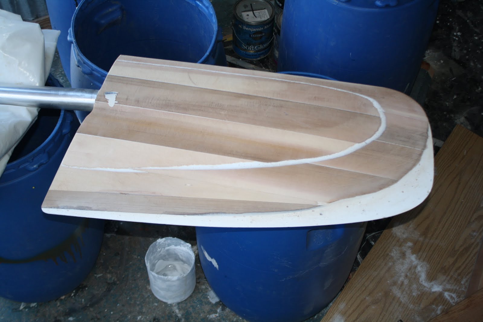
I realized the I had used the wrong profile template when shaping the rudders, so I needed to increase the chord length to improve the efficiency of the rudders ( I accidentally used the profile template that was intended for the dagger board rudders which was slightly rounded towards the lower ends). A mix of micro balloons and epoxy molded to the trailing edge did the trick. The good thing about keeping a nice messy shop is that you can always find stuff laying around to use to affect simple modifications......no need to stop work to go to the hardware store. Seen here, I made a quick mold out of some vac tubing sheet rock screwed to a Formica covered picnic table from the pop up camper.
The next step on the rudders will be to laminate the heck out of these things. I plan on running Kevlar along the leading edge with multiple layers of triaxial glass and unidirectional glass running lengthwise over that to create what will essentially turn out to be cedar core composite rudders.
The kick up rudder boxes are a fair amount of work but in the end, I think it will be worth the peace of mind that I'll have knowing that the rudders will be a little less vulnerable to hitting an obstruction and at the same time allowing the full rudder to be immersed below the water line.
Since the lower portion of the rudder boxes are completely sealed off, it required me to pre bond flanges to the inner sides that will allow me to bond the side in place. Inside the box in the lower left corner of this picture, you can see the glass reinforced bearing holder that has been bonded in place. Above this, located in the upper bulkhead you can see the backing plate made of 1/4 in. aluminum plate. This plate will be tapped with threads so that the upper bearing can be held in place from above by four screws. Once complete, the rudder shaft will be inserted from below and held in place with a collar and thrust bearing.
I've chosen to go with the optional kick up rudder boxes, mainly just for peace of mind. This option allows the rudder tube to be mounted inside a structure that can pivot upwards and back if the rudder hits an obstruction. Here, I am sanding the inside hull rudder box surfaces in preparation for laminating the bare core cell foam with 24 oz. triaxial glass and epoxy.
Like the "swing up" centerboard options, this rudder configuration creates whole lot of extra work. Hopefully I'll never have to worry about hitting anything with my rudders but if I do, maybe I'll be glad that I put forth the extra effort.
Two other points led me to choosing this rudder option:
1. It allows for clean, unobstructed boarding steps on each hull.
2. Since the rudder blade is completely submerged below the water line, there will be less likelihood of "ventilation" caused by air being sucked down the trailing edge of the rudder while at speed. (in regards to fluid dynamics, considerable drag can be attributed to trailing edge geometry just as much so as that created by a poorly shaped leading edge)
I's a bit hard to notice in this video but believe it or not, in windsurfing, a fin can actually "stall" and cause a spin out that would almost make you believe that you have lost a fin. You wouldn't believe that a fin could be driven sideways across the flow of water at 36 knots but it can.
Here's a somewhat confusing photo taken from inside the boat looking aft towards the kick up rudder box and boarding steps of the starboard hull. All of the seams have now been reinforced with 4 inch strips of DBM1708 tape and epoxy. Although the sail drives of the twin Yanmar 3YM diesels extend about a foot below the bottom surface of the lowest point of the hull, I chose to go with the "kick up" rudder option. I figure if I bang my props on a rock, at least I'll still have rudders......because a ship without a rudder is like a ship without a rudder.
Tucked upside down inside the aft portion of the starboard hull underneath the boarding steps, I am preparing the bottom of the stairs for laminating 24 oz. triaxial glass. About the only way to bond glass to a horizontal or vertical surface is to cut a template from butcher paper, transfer the shape onto the glass with a sharpy, cut out the piece of glass fabric then use 3M 77 spray adhesive to tack the dry glass in place. Once it's in place, mix a batch of epoxy and roll it on wet, let it soak in a bit then squeegee until you're convinced that all of the air has been removed between the foam surface and the saturated glass.
Below are a few photos of the starboard bath area. You may notice the absence of cabinet drawers. Reason being, is that I have decided to create simple openings that will provide places for waterproof containers. For durability, the edges of all openings will be protected with aluminum Tee molding:
Each opening is at least 2 inches above the bottom of each compartment so that any containers will remain inside the storage compartment during rough weather. Each container will be labeled with the contents. The mantra will be "if it's not in a container, its not on the boat". Not only will this force me to maintain order, in the case of capsize, the waterproof containers will also provide extra buoyancy.






 Posts
Posts


