12.31.2010

Modern art Hatch Openings

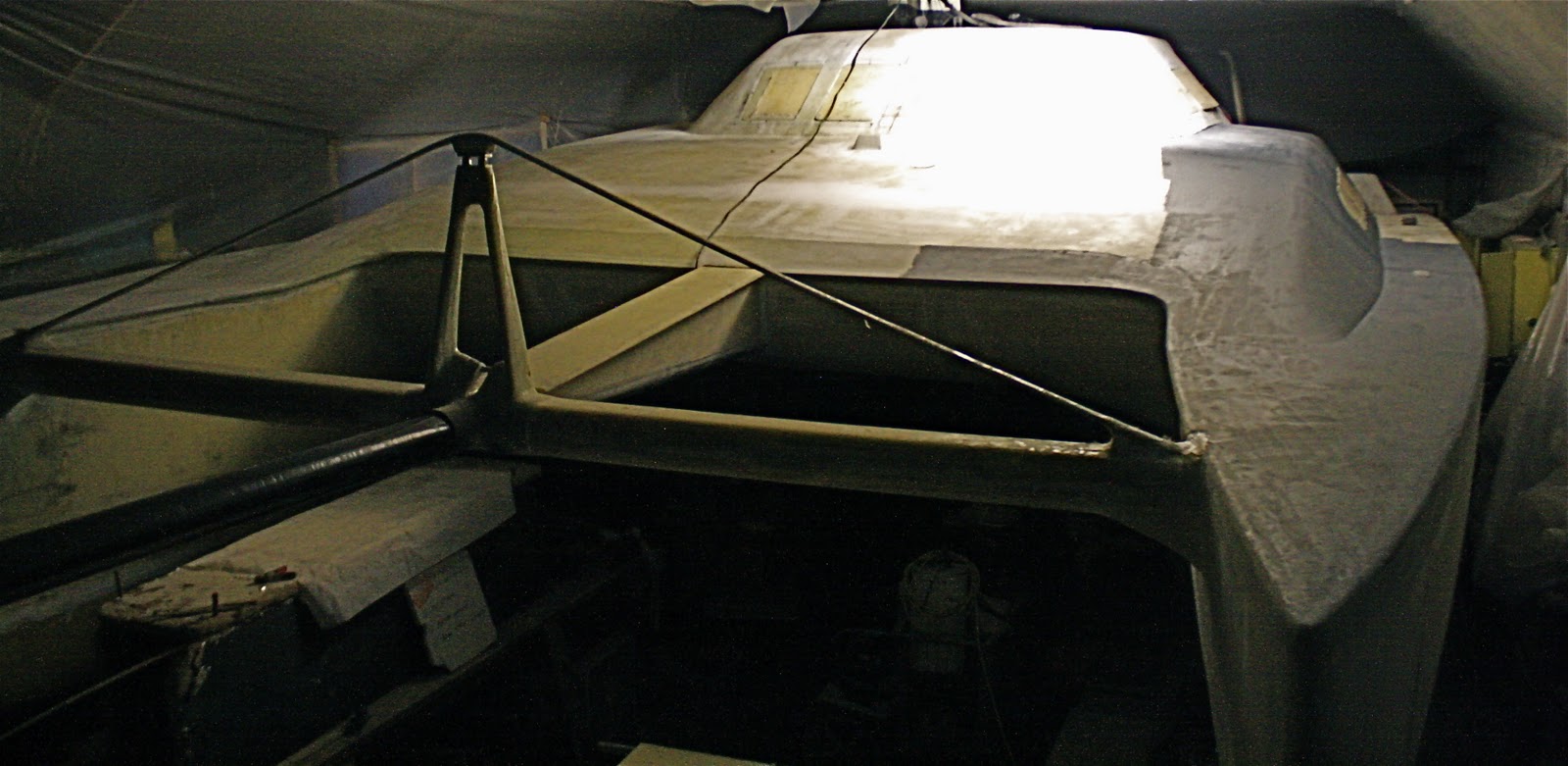
 I strengthened the edges of all of the hatch openings by routing out an inch and a half of deck foam then re-filling the void with a thixotropic mixture of aerosil, glass micro spheres and epoxy.


I then used strips of tough synthetic roof material as a mold to create nice smooth edges that will require little finish work.  I used flexible wood strips, springing them together to hold the edges in place.

 this method works really well.  The sharpy marks will be the drill holes and location of the hatch frames.


12.29.2010

Shame on Lewmar

flimsy hinge clutch attachment on new Lewmar escape hatches:

I can only hope that this failure was due to a worker using the wrong size rivet, otherwise, Lewmar should know better than to use such a failed design in the attachment method of the hinge clutch to the frame.


It is easy to see that the flimsy aluminum rivets were not long enough to even go through the flange on the hatch frame. 


This two part "spring/clutch" is attached between the two hinges and is supposed to keep the hatch from swinging wildly when opened. In my case, the second time I opened the hatch, the attachment broke off.  

This is very poor design. At close to a thousand dollars a piece, it is not unreasonable to believe that details like this would be so under designed. 

Yet another opportunity to improve upon the work of a manufacturer.......Tomorrow I will bring the escape hatch to the local farm and ranch hardware store and buy two beefy stainless steel fasteners to replace these two flimsy rivets......only down side will be galvanic corrosion due to dissimilar metals but I may not have a choice. 

12.21.2010

Got to have a place for the Frozen fish and some cold beer.


I took a little time to create a CAD drawing of the type of fridge / freezer that I want to have on board and I'm planning on building it in the next week.  I'm hoping that it will come out looking something like this.  I'll be chopping foam, slinging tape measures around like swords and knocking this thing out free style.


I've been doing a fair amount of studying about marine fridge freezer systems and I've decided to build my own.  A helpful book that I just read was "Refrigeration for Pleasure Boats" by Nigel Calder.  It is a pretty basic book but gives some nice illustrations of simple boxes.  I chose a full "Frigoboat" component system because I like the idea of the pre charged lines, electronic speed control option that reduces the compressor RPM to meet the demand and I liked the modular aspect.  Also, since I'm headed south, I'm using a keel cooler condenser to dump the heat into the water rather than heating up the cabin.  

12.20.2010

Coooooold


Here's my excuse for my delayed progress on the Cat.....It's fricking cold and I am a misplaced Southerner born and breed.
Here are a few projects that haunt me:
  1. Boxing in the swing up rudders
  2. building the top loading fridge freeze boxes with Frigoboat mechanicals w/ keel cooler
  3. glassing strips supports for hull floor boards
  4. finishing out all four state rooms
  5. coordinating the build of the mast, boom and standing rigging ( Ballenger Spars)
  6. Overseeing sail construction ( Doyle Sails)
  7. detailing engines:  exhausts, filters. through hulls, etc.
  8. installing R.O. watermaker
  9. Building out interior bridge-deck living space
  10. Electrical system ( planning on keeping it simple )
...........but who's counting?

12.11.2010

floor board strips

This is a shot taken about knee level from the inside of the starboard hull looking into the forward  cabin.  A cross wise lower hull stiffener will also be glassed in place mid ways between the forward bulkhead and the mast bulkhead.  Once this stiffener is in place, I will glass over the floor board strips that I have glued in place and which will support the floor boards. 

12.09.2010

Dancing super models


Since it's winter time in the Pacific NW, the main cabin has become my new shop.  I covered the floor with 6 mil plastic sheet to keep from getting drips of epoxy everwhere.

There are a total of 12 floor boards in this boat and each one will be glassed and vacuum bagged to save weight and just in case, to withstand the compressive forces of 20 dancing super models wearing high heels.....that's 40 high heels. Given the average weight of a super model of say 65 lbs, and the area of the average high heel being  1/2 in x 1/2 inch this introduces the very real possibility of sustaining pressures on the order of  265 lbs per inch ^2 on the composite laminate ........or further still if the dancers perform moves that require high stepping , the pressure of a dancer standing on one high heel may soar to 536 lbs per in ^2 . ......  Perhaps a placard next to the US coast guard "no discharge notification" should read. "When dancing, all Super-models should refrain from high-stepping along both the port and starboard floor boards".

If I do two panels at at time per day, that's only six days........"only six days he says!"  Like I always say, if it's cold and raining outside you may as well be vacuum bagging dance floor boards.....I'm always saying that......I wish I could stop saying that

Double  Vacuum lines


heating the interior of the boat to cure the two panels.


  260 # / in^2 potential destructive pressure.


12.08.2010

both of the twin diesels are in bed now

I distributed the load of each engine by supporting a 4 x 4 in three places and used a chain hoist to allow me to wiggle the engine into place. 

Starboard side engine resting in a gloss white engine bed.

12.07.2010

Putting the engines to bed

 2 x 6 cross beam with rolling trolley

 sliding the engine down into the hull

 Walking the engine down a plank to it's bed.

 Using a 4x4 positioned over the aft cabin hatch, I was able to inch the  port side Engine into its place......

In order to allow me to quickly diagnose possible engine problems due to oil or  fluid leaks, I decided to lay  down a  gloss white epoxy coating inside the engine compartments.  To do this,  I mixed 2 quart of A side epoxy with one quart B side epoxy then mixed 1 cup of Titanium dioxide powder along with 1 cup of cabosil to create a thixotropic hard coat epoxy "paint". I then rolled it on nice and thick.   Now I should be able to wipe this surface down clean every time I check the engines.


12.02.2010

Escape hatches


Each hull requires an escape hatch and rather than install them so that they extend beyond the hull exterior, it is suggested that a recessed flange be used to allow the escape hatch glazing to be flush with the hull.  These foam pieces will be glassed in place creating a rigid, flat  location to bolt the medium profile Lewmar escape hatches.


Engine comes out of it's crate.

Two brand new 3 cylinder, sail drive, diesel engines were removed from their crates.  Seen here is one of the Yanmar 3YM-20 engines. This particular engine is destined for the starboard side hull. For installation, I decided to just man handle the units in place through the cabin doors rather than cut and build flush hatches in the aft decks above boarding stairs.  If I ever need to re build them,  I'll just take the darn things apart and remove them bit by bit.

11.25.2010

Import Security Fileing...or else

A week ago, I mistakenly mentioned that my cat's mast had left the port of Tauranga, NZ on the ANL Bindana when in fact, this was when the mast was packed into the container.  The ship is still in port:  see link-

http://www.marinetraffic.com/ais/default.aspx?zoom=9&oldmmsi=636091168&olddate=11/24/2010%201:52:07%20AM

The US now requires that an Import Security filling ( ISF) be filed before any item is shipped and imposes a $5000.00 fine if not done.   I hope that the documents made it into the right hands........

11.23.2010

Decks and cabin tops sealed w/ Awlgrip

Deck primed and sealed w/ AwlGrip 545. One of the twin diesel engines can be seen below the bridgedeck awaiting installation. It will be nice to tuck them into their engine beds so I won't keep putting random  tools and clutter on top of the crates.


The cabin tops and foredeck seen here in 545 sealer. The gallon paint cans are placed on deck for scale. The black window covers are actually the cut outs with flat black paint. I set them back in place to allow me to heat the interior this winter.


11.19.2010

The Mast is aboard a Liberian ship

According to the Import Security Filling, the mast for this F-44SC catamaran is on a container ship named the ANL Bindana on her way from New Zealand, and can be tracked here:  http://www.marinetraffic.com/ais/shipdetails.aspx?MMSI=636091168

wish here well in her journey to the west coast of the United States...........

11.18.2010

Sealing the micro


First coat AWLgrip 545 Epoxy Primer on the port side deck. Rough fairing done with microbaloon/epoxy mix ; final surface fairing with System Three Quick-Fair. Minimum application temp is  55 Deg. F ...chances are not looking good. So I am officially switching over to building out the interior.

Hood River Weather :


Saturday

Nov 20

Cloudy with spotty showers40°Lo 27°

11.17.2010

Hammock testing


With the targa bar in place, I though it prudent to use a hammock to test structural integrity........a bit premature I might add. Not to mention the fact that under sail, if you fell out, you would have to tread water for the rest of your life.

starboard hull stiffener

Aside from providing a resting place for interior floorboards, each hull requires three lower hull stiffeners. I pre cut all reinforcement material with my best pair of titanium scissors and after that job, my forearm would have made Arnold Schwarzenegger's look like a girly man.

Here's the math:

6 stiffiners x 6 strips of uni + 12 overwrapps of 3 ply 24oz.  Triaxial glass = 72 layers of reinforcement

This photo shows the mid ship, starboard hull stiffener looking towards the stern. The left side of the photo shows the centerboard case while the right shows the interior hull shape as it transitions itself into the underside of the boat.

11.15.2010

Marine Refrigeration system

I decided upon a modular marine refrigeration system which will allow me to build  the type of frig freeze unit that I want.  This unit weighs in at only 10 lbs and with proper box design, I plan on building a deep freeze to stockpile fish along the way. I'm hoping there will be a few fish left in the ocean come this summer when we launch.


Rather than use the conventional condensing unit,  I opted for the "keel cooler". This dumps the heat that is being removed from the fridge / freezer into the water on the outside of the boat rather than inside the cabin  interior. ( no need to have a heater in your boat when your in the tropics )


Unfortunately, this condensing unit weights approximately 1,200 lbs. is 4 ft tall and about 10 feet in length. 

11.08.2010

Early Christmas......


1.   After opening bag
2.  Ripping off the breather
3.  pulling the thin perforated film
4.  the best part: peeling the peel ply
5.  showing the uniglass along the leading edge. ( this goes into "tension" when the targa bar is loaded)
6.  Overlapped the tri glass along the trailing edge ( this goes into "compression" when loaded so 6 layers provides a little bulk and creates optimum configuration for compressive forces)
7.  a little trick......use a stapler to keep the glass in place in the wet layup step
8.  placed a couple of 1x2's in the void to help prevent concavity.

I'ts nice when things work out!   

11.07.2010

rudder bagel and cream cheese

Had a fun time using my Grandad's old chisels knocking out chunks of cedar to allow the rudder bars to nest into the two cedar core halves.  After carefully measuring the desired location of the rudder shaft, I scribed the outline with a sharpy pen and then performed some free hand skill saw action to cut the lines......holding my mouth just right to judge the depth of cut as I went along. After that, I slathered the rudder halves with a mixture of cabosil, microbaloons and epoxy like a big bagel with cream cheese, bagged it, placed it in my curing oven and let the pump run until morning.

Clothing the final Targa bar piece

Trimming the 24oz. Triaxial glass cloth for the Starboard targa bar upright.


 In the bag.... (note: Vac pressure can crumple just about any object containing an open cavity and since these targa bar uprights have hollow cores with a stringer running lengthwise, I chose to run a small tube into the bag and into the internal void. This allowed me to introduce a controlled amount of atmospheric pressure during the curring phase to prevent creating concavities in the sides of the members. )  


Turned out fine...................

11.05.2010

flying cedar shavings


photo 1 :  western cedar rudder blank ( got a little heavy with the epoxy an micro but I wanted to make
                 sure that I didn't have ANY voids. )

photo 2 :  after an hour with a power planer. ....fun time shaping a Clark Y airfoil from nice smelling
                wood.

Photo 3 : finished shape

Photo 4 : detail showing my emergency tiller option.  I decided to just machine a hex head on the end
               so that I can make an emergency tiller by just welding a deep well socket onto a tube.

It's a shame that these rudders have to live their lives under the back of the boat. Seeing how nice they look makes me want to varnish them and use them as figureheads. Next step is to lay a little kevlar along the leading edge and sheath the whole thing with triaxial glass and epoxy.

Bonus: I plan on sweeping up the pile of cedar shavings, sewing them into a big pillow case and making a dog bed for Daisy.

11.04.2010

Targa bar corners


To help with shaping, I used a sharpy pen to mark a center line guide curve on the ends of the foam


I stayed up many nights trying to come up with a brilliant way to create the 8 inch radius corners of the targa bar.  Although my method allowed me to create a nice transition, it required the cutting, gluing and shaping of over 20 pieces of corecell foam.  The end result turned out nice but this was mainly due to persistence not brilliance.  Sometimes, simple solutions are difficult to find.  The next step will be to laminate the exterior of both targa bar uprights then glass the entire assembly onto the stern of the boat.

11.02.2010

rudder boxes

The "Jeffa" spherical rudder shaft bearings are being bonded into the kick up rudder boxes.

The lower bearings came pre bonded into large diameter fiberglass tubes and require generous fillets with multiple layers of triaxial glass over this; bonding them into position.

The upper rudder shaft bearings will be installed in the sub bulkhead seen on the rudder box on the left. ( it hasn't been glued in place so it's just sitting a little crooked in the box )

Test fitting the targa bar.

It was a bit of a balancing act positioning the targa bar pieces in place.  Hidden from view on top of the cabin are two car batteries sitting on top of the ends of the two 2 x 4's acting as a counterweights which allowed me to hang the targa cross bar in place.

Part of the reason for performing this trial fit is to determine the shape of the two corners.  This will no doubt require some creative foam shaping. Once these two corner core pieces are formed, I'll pull the uprights down, glass them and reinstall them for the final install.